Filters and mirrors in laser applications
The use of a laser as an illumination source in fluorescence applications requires special attention to the problem of the optical path. Special attention needs to be paid to the coherence of light, small beam diameter, light polarization, and optical power. In some cases, the cone angle ( incident angle ) and the scattering present in the system are important factors to consider in the design of the optical path. Although the entire optical path needs to be considered in the design of the optical path, this article will focus on the filters and beamsplitters used in the optical path. Compared to the epi platform, the laser system, although most of the three lenses listed above, differ greatly in their configuration. These filters and lenses are usually and must be mounted on a base / cube, and their position in the optical path varies from system to system. Fire Alarm By Room,Smoke Alarm By Room,Room Smoke Alarm,Room Smoke Alarms Guangdong Isafenest Co.,Ltd. , https://www.isfenest.com
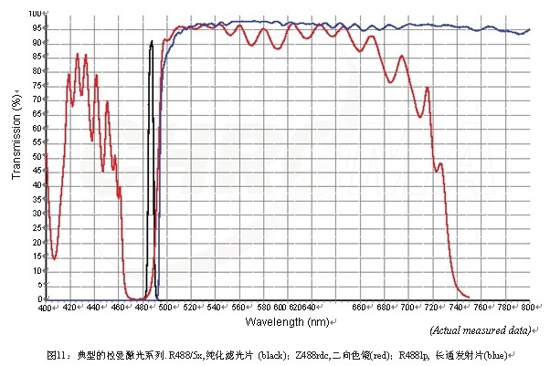
There are three kinds of light components playing an important role in the classic elevation position lighting configuration : excitation film, dichroic mirror / beam splitter, and emission film. Typically these lenses are mounted on a cubic box base that can be inserted or removed from the microscope as needed.
In this standard fluorescence microscope example, the exciter can block all of the light from the deep ultraviolet to the near infrared non-fluorescent dye excitation band. Typically this is a bandpass filter with a full width at half maximum (FWHM) of 30 to 60 nanometers . In standard microscopes, these lenses do not have surface flatness specifications or transmission wavefront requirements. The wedge can be very large ( usually less than 8 arc minutes ) and the scratch / poke size is at least 80/50 . There can be pinholes that are too small to be measured or observed. Usually there is no need to worry too much about the autofluorescence of the sample because the lens is placed outside the imaging path. This lens is generally not AR-coated and uses float glass as the substrate. These excitation plates are designed with zero incident angles.
In laser applications, the specifications of most filters are significantly different. The purification filter ( excitation sheet for the laser ) must only filter the unwanted bands from the laser. There are still many users who think that the laser does not need to purify the filter, which is not correct. Almost all plasma lasers produce multiple lines of different power, and the new generation of diode emission spectra has a wider full width at half maximum. In addition, they may also have noise away from the main line. Diode-pumped solid-state lasers typically have very narrow emission spectra in their output, but they can be contaminated by pump sources or major lines. For these reasons, all laser systems are tested for signal-to-noise ratio with or without a purification filter. The transmitted wave front must be better than one wave per inch, although in some applications the requirement is 1/4 wave per inch or better. The wedge must be small, within one arc, and without pinholes. The autofluorescence of the sample must be considered in advance and the scratch / puncture specification must be no less than 60/40 . These filters typically have a full width at half maximum of 10-20 nm, are ground and polished, and are AR coating on either side, rather than an interferometric coating. Although standard laser applications use float glass as a substrate, Raman and other applications may require fused silica glass to reduce any autofluorescence that may be present in the optical path. The purification filter is designed to accommodate an angle of incidence of 3-5 degrees to ensure that the reflected laser does not return to the laser oscillation chamber. See Figure 1 below. 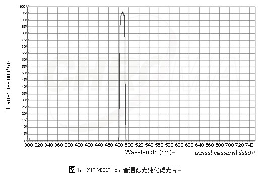
The second type of lens in the configuration is a dichroic mirror, also known as a beam splitter. In a generalized epi system, it usually has the following specifications: less than 10 waves per inch of surface flatness, less than 1 wave per inch . Transmitted wavefront, less than or equal to one arc of wedge, 40/40 scratch / scratch. The dichroic mirror should be made of fused silica glass because it is placed in the excitation and reflection paths of the epi system. For standard applications, the lens does not need to be a lens. These lenses are designed to grow through filters ( reflecting short-wave light and transmitting long-wave light ) or short-pass filters ( transmitting short-wave light and reflecting long-wave light ) . In a standard microscope configuration the dichroic mirror is designed to have an angle of incidence of 45 degrees such that the angle of the excitation light changes by 90 degrees.
In laser applications, the dichroic mirror more stringent specifications: There is less than 1/2 wave per inch prior to coating the surface flatness, less than 1/4 of the transmission waves wavefront distortion, less than 5 arc seconds wedge, And usually 40/20 scratches / cuts. All laser lenses require an anti-reflective coating to reduce secondary reflection and scattering of the laser while enhancing transmission. Most commercial microscopes are known as 1 mm thick dichroic mirrors, which require thicker fused silica glass to more easily meet these requirements. For these reasons, laser applications often use thicker lenses / dichroic mirrors. While most laser lenses are designed to have a 45 degree angle of incidence, some currently popular or even newer versions of confocal microscopes use 10-15 degree incident angle lenses to increase reflectivity ( ie, increase blockage ) and minimize polarization effects. All of the above specifications are considered to be minimal requirements, as these lenses are also required to meet higher standards in certain applications.
Another factor to consider for dichroic mirrors is the polarization of the laser. The design of the lens requires no polarization at zero angle of incidence, but any lens has a polarizer at a certain angle of incidence, and the angle of incidence depends on the specific design. Therefore, all laser lenses need to consider the polarization properties of the laser. See Figure 2 . 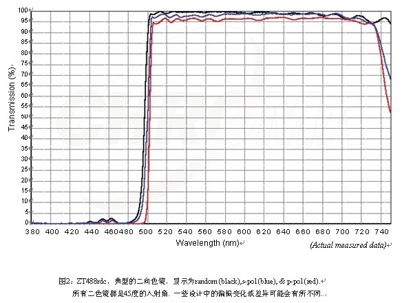
Another element to consider for a dichroic mirror is that stress is applied to any substrate, such as fused silica glass. This stress may be so small that it is not noticeable, but it is sufficient to cause extreme astigmatism in the beam. A thicker substrate can basically help solve this problem, but it may not be enough by just relying on it. Therefore, most manufacturers have a special way to neutralize this stress, and the reflective properties of these lenses must be strictly balanced. It should be noted that the transmission wavefront is dependent on the flatness of the outer surface of the substrate and is generally unaffected by any coating.
Another possible cause of stress is the method of installing the lens into the system. The surface of the 45 degree deck on which the lens is placed should be polished to resemble the surface flatness of the substrate ( e.g., 1/2 wave per inch ) , and any object that supports the lens in its position cannot produce any unevenness. pressure. These effects are most pronounced in TIRF ( Total Internal Reflection Microscopy ) and may require the replacement of a standard microscope base with a fully customizable cube base.
The launcher is the last lens in the configuration and is often referred to as a UV filter. The main function of the lens is to prevent the excitation band light from reaching the detector ( human eye or electronic detection device ) . Its second function is to transmit the desired fluorescence from the target dye. This means that the emitter must have high extinction to block any light that passes through the excitation sheet. Blocking is usually measured by optical density (OD) , which is the logarithm of transmittance (T) , which ranges from OD 3 to OD 6 in a wide range of applications . The lenses are either band-passed or long-passed. Typical specifications are: less than one wave per inch , less than one arc, 60/40 scratches / cuts. The anti-reflective coating can be selected according to the specific application.
For laser applications, the minimum requirements for the emitter are similar to the above definition. Except for one point, the blocking of the laser beam should be a minimum of OD 6 and in all cases an anti- reflective coating should be used. These emitters are also designed to have an angle of incidence of 0-5 degrees, just like many modern wide field systems to reduce internal reflections. See Figure 3 below . 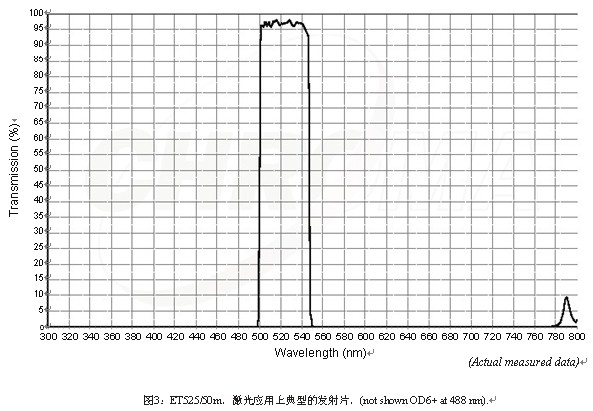
Standard laser scanning confocal system
A typical laser scanning unit is required to meet the specifications listed above and also to consider whether the emitting sheet is placed in the runner or in the split unit. If the confocal microscope has only one detector ( usually a PMT ) or uses a rotor wheel to sequentially image, the emitter for each laser beam must only filter that laser. Multi-detector systems use a split spectroscopic dichroic mirror to control light. These dichroic mirrors do not need to meet more specifications than conventional lenses, but in some applications an anti-reflective coating is required to ensure image quality.
As mentioned above, some new generation laser scanning units use a common dichroic mirror with an angle of incidence other than 45 degrees and possibly 10-15 degrees, but the spectroscopic dichroic mirror is usually a 45 degree angle of incidence. .
Multi-pinhole confocal microscope
Current commercial Nipkow Disk confocal microscopes have two completely different beam paths. One is to use a primary dichroic mirror to reflect the laser so it is very similar to a standard confocal configuration. Another type is to use a primary dichroic mirror to transmit laser light onto the sample and then reflect the excitation light onto the detector ( usually a CCD camera ) . The design of such transmission dichroic mirrors is very difficult for a number of reasons. Dichroic mirrors are somewhat more difficult to design and manufacture because of the requirement for very narrow transmission bands and wide reflection bands. This design means that even more lasers will eventually be reflected onto the detector ( also at different angles ) , so special emphasis is placed on the filtering capabilities of the emitter. Since these transmissive lenses are placed in the focusing path of the optical path, the thickness of the substrate is limited, which makes the wavefront distortion control more complicated. As shown in Figure 4 .

Total internal reflection fluorescence microscope, TIRF
The initial design of the total internal reflection fluorescence microscope was to use a prism to direct the laser beam to the cell adhesion junction. There are problems that often require calibration, but from a filter point of view, it is more straightforward because the reflected laser is not collected by the objective. However, the development of a total internal reflection fluorescence microscope through the lens finder brings about different environmental conditions, that is, the laser excitation light is actually absorbed by the objective lens. Therefore, the laser can be reflected back into the optical path without loss. Reflected light requires a dichroic mirror and a launch sheet in a total internal reflection fluorescence microscope application that can handle a large amount of reflected laser light. The laser can be dangerous to anyone looking into the microscope, so it is usually filtered out by laser blocking equipment.
As mentioned earlier, the reflected wavefront distortion (RWD) of dichroic mirrors in total internal reflection fluoroscope applications must meet fairly stringent standards, typically with surface smoothness of 0.1 wave per inch and transmitted wavefront distortion. Start with a 0.1 wave substrate per inch . Care must be taken to ensure that the coating used does not give the substrate more pressure than acceptable levels. Since systems may vary, the surface smoothness may be required 0.25 to 1 inch per wave after plating.
Total internal reflection fluorescence microscope apparatus, the sheet must be greater than the emission blocked OD 6, and in many applications even to reach OD 8. This was considered impossible only a few years ago, but it is now quite common due to the use of advanced coating techniques and very special flaws.
The high angle reflection caused by the system design makes the total internal reflection fluorescence microscope imaging quite complicated because the interference filters are designed to have an incident angle of 0-5 degrees. Light that exceeds these cone angles causes the filter's cut-on to shift toward the ultraviolet direction, ie toward the laser source. Therefore, high angle excitation light in such systems requires that the emitter sheet have a certain cut-on red shift to avoid the above-described offset effect of the desired source while still maintaining a complete blocking capability. Another option in this context is to use an absorbing glass that does not rely on angular variations, but can greatly reduce the transmittance of the filter.
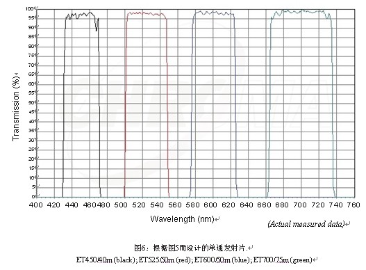
In the current total internal reflection fluorescence microscope system through the lens viewfinder , it is very common to use the emission sheet in the cube box ( base ) or near the lens dichroic mirror, and place a second in front of the detector emission sheet runner. Launcher. Placing a good blocking launcher in the cube also greatly increases the safety factor to prevent someone from accidentally looking into the microscope without a laser lock and getting injured. This dual-insurance launch design is absolutely necessary under some systems, but not necessarily in another system. It should be noted here that the standard very narrow notch filter is not very effective in these applications because this type of filter is very sensitive to the angle of the incident light. See Figure 5 and Figure 6 below . 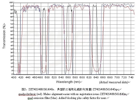
Multi-optical subsystem, two-thirds of the laser system structure
The development of two-photon imaging systems that satisfy early theoretical parameters ( using high-power pulsed lasers to excite fluorophores at two excitation wavelengths ) presents significant technical challenges for filter manufacturers. For these systems, in non-scan mode, the primary lens should be short-pass designed to reflect long wavelength bands while transmitting short wavelength bands. Such lenses must be designed to have a relatively high efficiency of reflection and transmission, and to ensure that the incident pulsed light does not have any dispersion, as this will significantly reduce the peak power. This new technology also means that blocking filters in these systems have a maximum blocking effect on longer wavelength bands, while single-photon laser microscopy is just the opposite of short-wave blocking. The new filter design must be developed and refined over time to meet the OD 8+ level required for laser blocking that is currently required within all parameter adjustment ranges . See Figure 7 below . 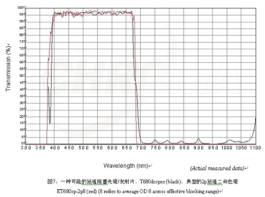
In order to further improve the design of the filter, many people want to use second harmonic (SHG) imaging and 3 photon excitation, which require dichroic mirrors and emitters to transmit light in the ultraviolet range. This is probably the most difficult part of the design, but it has now been achieved through interference techniques. As shown in Figure 8 . 
More users use non-rescan detection (NDD) systems that transmit signals that do not pass through the main dichroic mirror. These systems typically transmit fluorescence directly from the sample to the detector. At the beginning of the optical path ( see Figures 7 and 8 ) , the detector or the front of each detector in the multi-detector system is fitted with a bandpass transmitter, which may be a short-pass transmitter to block the laser. These are usually mounted on the cube base to simplify the beam path. As shown in Figure 9 . 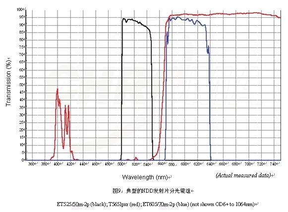
Coherent anti-Stokes Raman scattering (CARS) microscopy 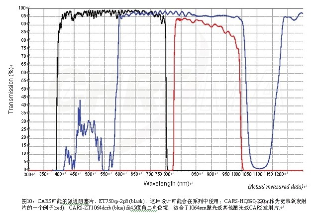
Raman spectroscopy
Laser trap and diaphragm 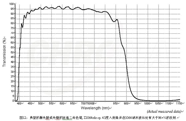
Flow Cytometry
In summary, laser lenses must be designed to be different from standard wide field filters and lenses. Despite the fact that most laser lenses are very good in wide field applications, SLRs are not necessarily correct, as in the different specifications in the case above. In every laser application, the difference in design and construction is not too obvious for the end user. However, in most experiments, if these specifications are not met, these differences will be noticeably painful, especially in more demanding applications such as total internal reflection fluorescence microscopy, Raman microscopes and more. Photon microscope.
Senior Applications Scientist
Chroma Technology Corp.